
Additive manufacturing is an excellent method for rapidly creating prototypes of metamaterial composites. We’ve sung the praises for 3D printing for its ability to help quickly iterate designs and integrate smart manufacturing into our systems.
But what happens when you need to create high-volume prototypes even more quickly? As Multiscale’s work with NASA matured, a necessity for fast fabrication of metamaterial composite sandwich panel cores became apparent. We needed a scalable, fast, and efficient manufacturing method that would suit our particular R&D requirements. The answer? Compression thermoforming.
A need for rapid high-volume prototyping
Thermoforming was determined be the most viable path to carry on prototyping our metamaterial composites cores while increasing volumes efficiently. But there are always challenges when it comes to change, and in this case, it was cost and quality.
New molds would be required for each design iteration and potentially for each type of material being tested, of which there are many. Molds produced via contract manufacturers don’t come cheap, and these manufacturers usually require large volume orders.
Often, vacuum thermoforming creates large variations in plastic thickness depending on the mold – something we’d not have much control over and wouldn’t be able to see until we got the parts in our hands if we outsourced manufacturing.
What we needed was a thermoforming machine that we could control ourselves in order to manage quality and production turnaround times and, importantly, one that wouldn’t break the bank.
Building our own compression thermoformer
With limited commercially available options that fit our needs, we decided to build our own compression thermoformer. Using t-slot framing, infrared heaters, heavy duty linear actuators, an ATmega328P microprocessor, and a host of other components and sensors, the Sheet Transport and Material Pattern Enhancement Robot (STaMPER) was created.
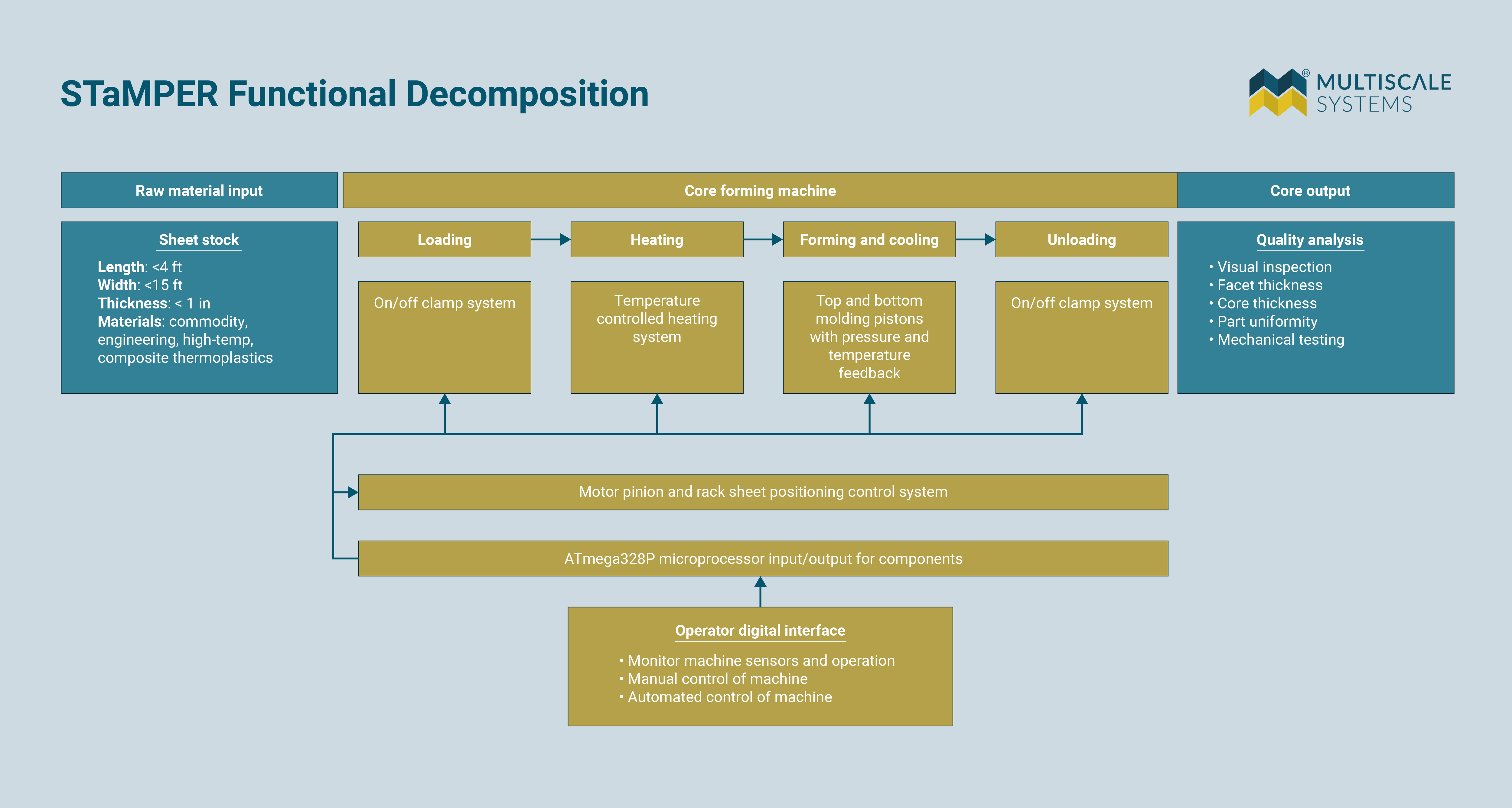
Here’s how STaMPER works. First, plastic or fiber-reinforced plastic sheets (thermoplastics) are loaded into the clamping system. The sheet is moved in steps under the heaters over a set period and at a particular temperature, depending on the type of thermoplastic being used. Once heated, the sheets are moved to the compression molding system, which uses a top and bottom mold to shape the softened plastic. The part is cooled a certain amount, the molds release, and the process is repeated for the length of the sheet until the entire piece is patterned.
The heating and molding are performed on discrete sections of the material as it moves through the machine, as opposed to an industrial thermoformer that heats the entire sheet and then forms it in one go.
Vacuum thermoformer vs compression thermoformer
Many manufacturers use vacuum thermoforming – meaning only one mold is used and the softened thermoplastic is pulled down onto it using a vacuum. The mold itself contains numerous tiny holes that air can be moved through to pull the sheet down.
By contrast, STaMPER is a compression thermoformer, meaning that while it still uses heat to make thermoplastic sheets pliable, it relies on compressing that sheet between two complementary molds to produce the desired part. Compression thermoforming is quieter and involves less mold tooling time than vacuum thermoforming.
The functional decomposition diagram below shows a workflow of the STaMPER process.
Dialing in the design
A huge consideration when designing STaMPER was material access and cost. Components were selected based on their availability and affordability.
With the number of components required, the machine was organized into modules:
- Sheet-feeding mechanism
- Heating module
- Compression molding module
- Operator interface controls
Sheet feeding
We initially built the sheet-feeding mechanism using rollers, but this method was quickly found to be due to the uncontrolled increase in frictional force between the rollers and the sheet as it transitioned from a solid to a viscous liquid under the heat. The changing frictional force caused the feeding motors to be unable to precisely control the displacement of the sheet. We replaced the rollers with a clamping system set on a track. The track moves the sheet through the different modules with its movement controlled by a stepper motor with a pinion gear connected to a gear rack on the track.
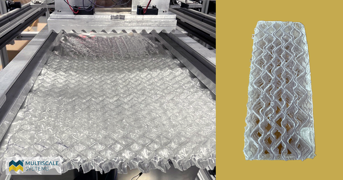
Glass fiber and thermoplastic plies consolidated in the part shape using STaMPER.
Moving to a track system dramatically improved the machine’s ability to perform precise, repeatable steps that could be tuned by the operator.
Heating
The heating modules were designed to support a variety of thermoplastics with melting temperature ranging from ~150°C (~302°F) to ~400°C (~752°F). For this reason, 1,000-watt ceramic infrared heaters, coupled with high-temperature thermocouples, were used to quickly elevate the temperature of the plastic before forming.
The temperature profile of the plastic as it heats up and cools down plays a vital role in the quality and mechanical strength of the formed part.
If the raw sheet doesn’t have enough heat input it will require more force to be pressed into shape, potentially causing the sheet to tear as it’s molded, or to only be partially molded. If the raw sheet has too much heat input before molding it can cause the formed part to have greater differences in wall thickness or even cause the sheet to tear before molding begins, due to internal thermal stresses. Knowing the temperature profiles of your materials and being able to minutely control the machine’s heating module is crucial in creating quality, usable parts.
Molding
The molding module requires the precise machining of molds in order to transfer patterns with tight tolerances. We brought our mold tooling in house, fabricating them using a CNC mill. To help reduce costs, and since the metamaterial composite patterns we’re embedding are repeatable, we use relatively small molds.
Tooling cost is primarily driven by the size of the stock material required, the amount of chip material removed, and the operating time of the machine. Typically, molds are about 9 in x 4 in and have an average machining time of 24 hours per set, and about 50% chip waste. This size of mold translates to approximately $120 for stock aluminum and about $500 for machining labor. Considering most contract manufacturing companies charge upwards of $20,000 for new mold tooling and require minimum order quantities, our machine allows us to rapidly iterate mold designs for testing at an affordable price point.
STaMPER’s molding module has a decent travel distance for both the top and bottom molds which can be adjusted to account for the sag of different materials as they’re transferred from the heating module to the molding module.
Operator interface
The operator digital interface is a crucial design piece that allows an operator to communicate with the machine. Initial trials required the operator to send command lines through a serial port. To make the interface more user friendly, we built a graphical user interface (GUI) to control the machine through a digital screen with buttons and text fields.
The addition of the custom GUI dramatically improved the ability to control the different features of the machine and monitor sensor responses. It also allowed new features to be added quickly to the machine to improve the control through simple firmware updates.
STaMPER leading the way for fast, efficient prototyping
Over several iterations of designing, building, and testing our compression thermoformer to improve functionality and robustness, we can now rapidly prototype new metamaterial composites in a high throughput fashion – for the fraction of the cost and turnaround time of outsourcing to commercial thermoformers.
This new asset is fundamental to efficiently develop and test new designs for future projects and for IP development.
 Shawn Aalto is an R&D Mechanical and Materials Engineer at Multiscale Systems. He specializes in material design, simulation, and manufacturing.
Latest Lab Notes

News /
July 18, 2025—Multiscale will engineer functionally-graded alloys tailored for molten salt and liquid metal environments, leveraging its hybrid manufacturing systems to produce nuclear-grade material performance.
News /
March 11, 2025 – Multiscale Systems to showcase cutting-edge industrial innovation during StartUp Week Worcester 2025.

News /
Multiscale Systems receives Massachusetts manufacturing award in recognition of outstanding leadership skills in the manufacturing industry.

