The terms additive manufacturing and 3D printing are often used interchangeably, but the kind of process or material being used can vary drastically. Using these catch-all terms can result in obscuring the differences between methods, processes, materials, and ultimate end-use cases.
And these differences matter. Depending on requirements like porosity and fatigue resistance, you’ll get wildly different results depending on how you go about additively manufacturing your metal part.
What is additive manufacturing?
Additive manufacturing (AM) is used to fabricate parts from a variety of materials including metals or plastics, and the raw feedstock can be in the form of filament, powder, or wire. The resulting part may require post processing in an oven or furnace, or even machining with a CNC. Depending on the material and process, the final part can be used in applications as varied as toys, blow mold tooling, or as components in jet engines or nuclear reactors.
Metal additive manufacturing
For many applications, plastic parts can’t perform the way that metals can. High temperatures and high strength applications, or parts that need to be electrically or thermally conductive, are much more likely to be produced using metal.
Conventional metal manufacturing methods like forging, stamping, rolling, and extrusion are well suited to producing uncomplicated, high quantity parts. But what if you need complex parts cost-effectively produced in low quantities? This is where AM shines – stepping in to produce parts that conventional manufacturing can’t.
But how do AM metal parts compare to traditional parts and what are the different ways that metal can be 3D printed? In this article we talk about three different metal additive manufacturing methods – bound metal, laser powder bed fusion, and hybrid additive CNC – and discuss the relative benefits and disadvantages.
Method 1: Bound metal 3D printing
The most common type of bound metal 3D printing uses Fused Filament Fabrication (FFF). FFF is how most people envision 3D printing – a filament of plastic is fed into a heated nozzle mounted on a moveable platform and heated plastic is deposited onto a prepared bed where the part is built up, layer by layer.
Limitations of FFF come from the nature of the extrusion process – not only in speed and the complexity of the design, but in the porosity and strength of the final part. The filament is generally extruded as a solid tube of material, so it has a circular cross-section. As these noodles are being laid down in layers, they lay on top of each other (Figure 1). This method will always leave little gaps in the structure, and these gaps can lead to failure modes if the part needs to be put under any kind of load or stress.
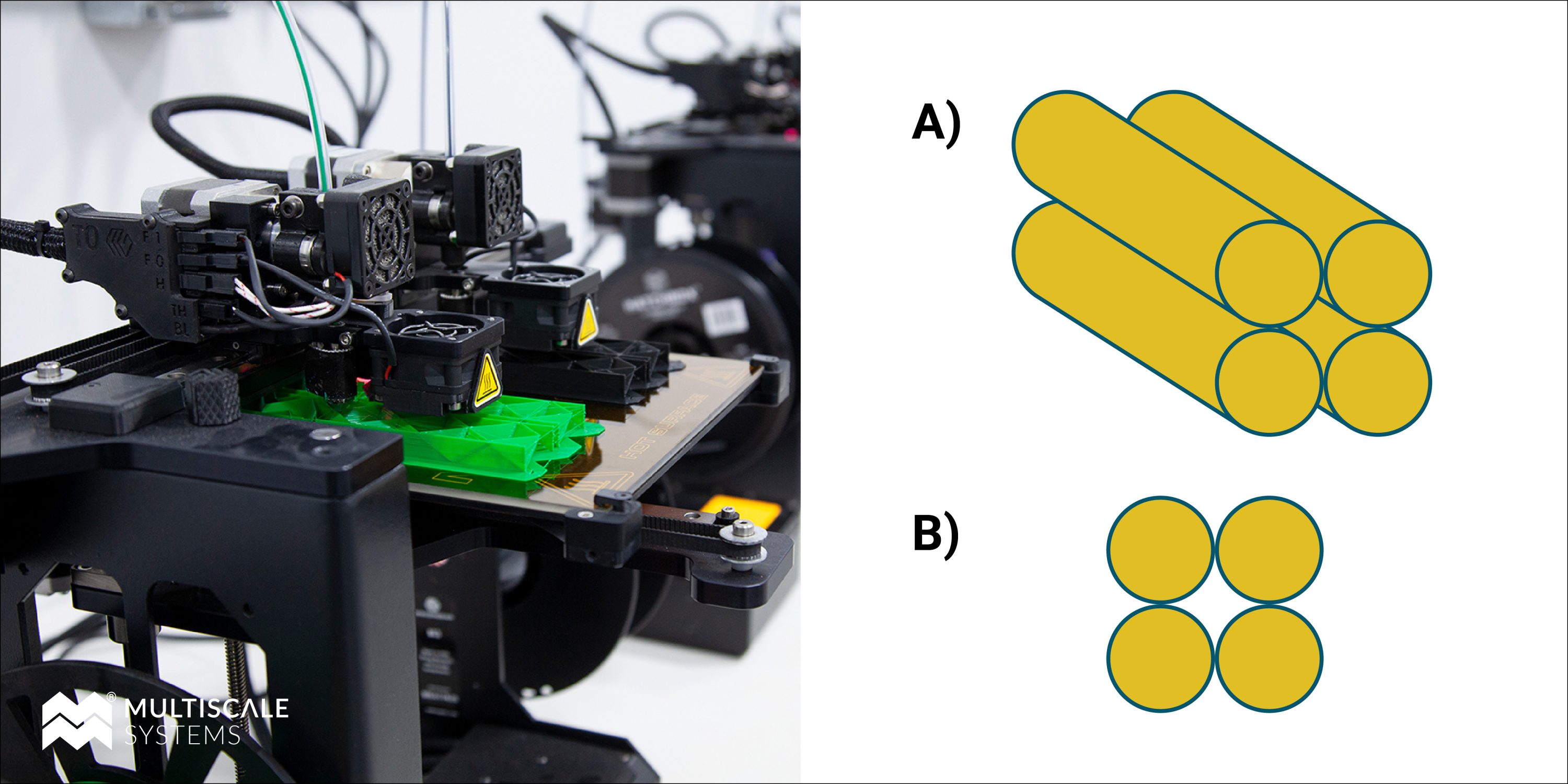
Figure 1: FFF printing. Left: snapshot of FF printer in action. A) 3D schematic of how filament is deposited layer by layer. B) Final part cross-section showing the gaps or pores.
Metal FFF
For plastic FFF, the material simply cools and fuses together. To make a bound metal part using FFF, a special filament with embedded metallic particles must be used (BASF or The Virtual Foundry are good examples of source material suppliers). These materials print just like plastic, but afterwards the non-metallic binder material is subjected to a series of post-processing steps to make the final all-metallic part (Figure 2). The filament binder that contains the metal is dissolved using a special chemical solvent or it is burnt away using thermal debinding. After debinding, a furnace/kiln/oven treatment subjects the part to an even higher temperature to sinter the metal particles together (Figure 3).
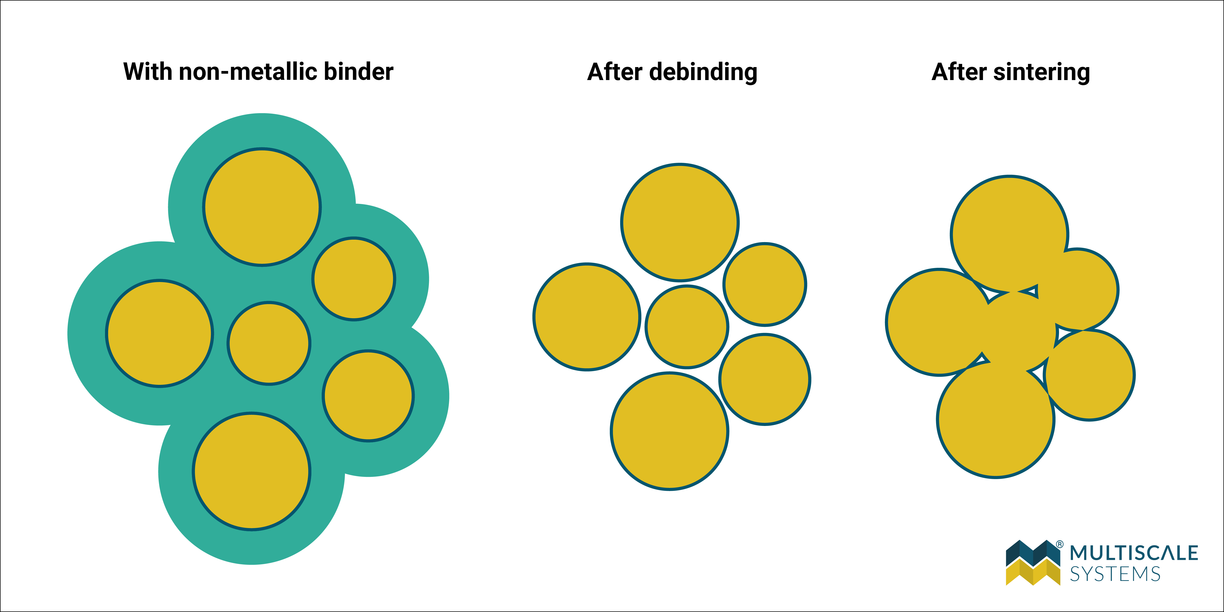
Figure 2: How sintering turns a bound metal part into an all-metal part. Left: the metal particles are bound in a material that allows the part to be printed using FFF. This non-metallic part (shown in green) is then sent for debinding, either using a solvent wash to dissolve the binder or using heat to burn away the binding material. This process brings the metal particles closer together, causing the part to shrink. During sintering the metal particles do not melt, but they deform and diffuse to close the gaps and lower porosity, eventually resulting in an all-metal part.
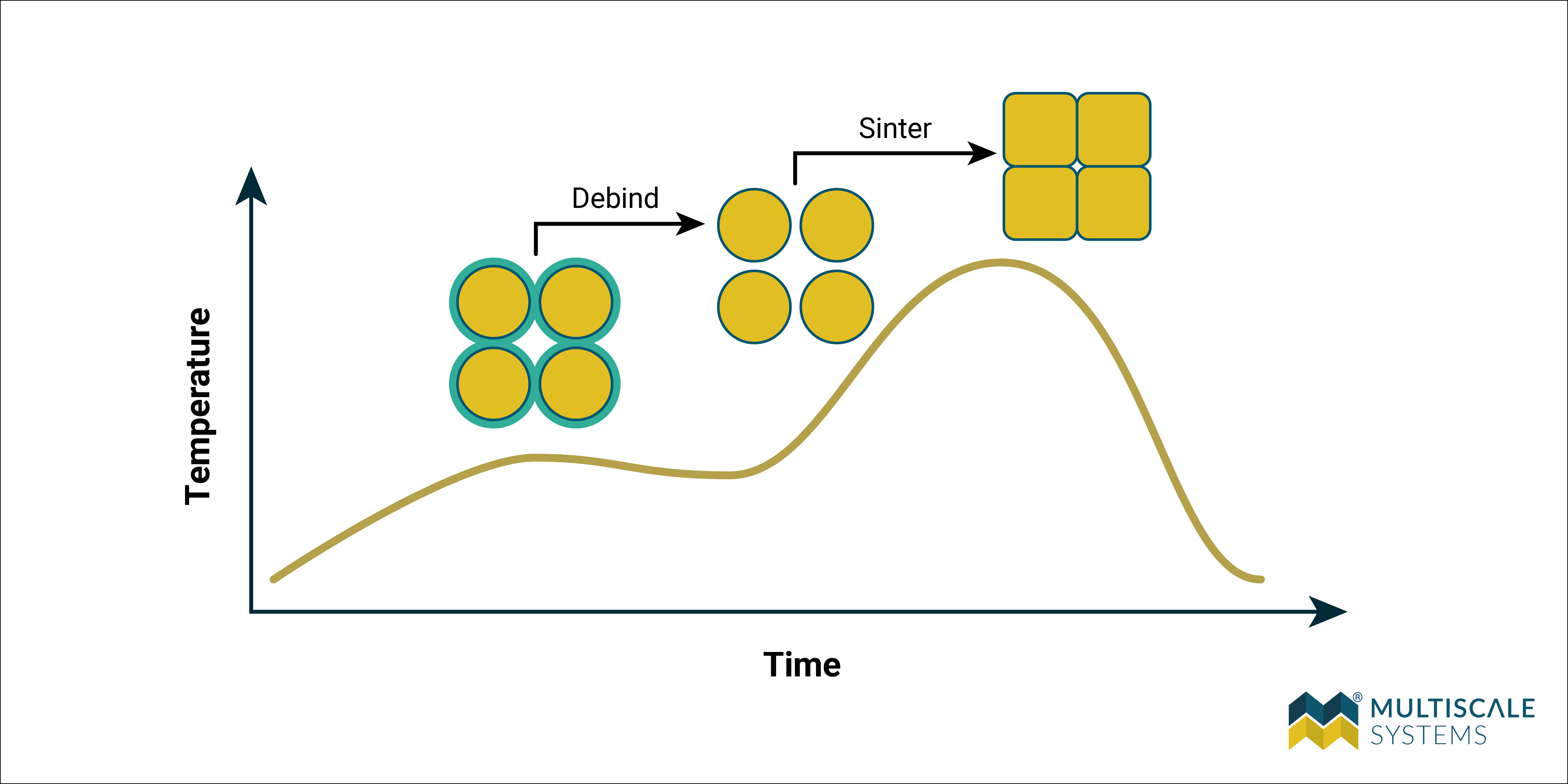
Figure 3: Furnace temperature as a function of time. In thermal debinding the material first burns away at an intermediate temperature, before the furnace increases the heat to perform the sintering process. The complex interplay between the material properties of the metal determines the proper temperature profile, which is tailored to each particular metal powder.
This process results in a part that is now entirely metal, although it still contains porosity that is associated with the FFF process. There are better methods for creating bound metal parts, such as binder jet 3D printing, which can reduce the porosity but still requires the debinding and sintering process afterwards.
Bound metal AM has the benefits of being relatively cheap and easy to produce. Metal parts can be made using simple printers, including the kinds that hobbyists might use for FFF. The result is a part that is denser, stronger, and stiffer than plastic.
Disadvantages of metal FFF include porosity and layer adhesion. While sintering densifies the part, most metal FFF parts only achieve 80-95% density of a conventionally manufactured solid metal component. For those parts that have stringent fracture/creep/fatigue/strength requirements, porosity can be a deal breaker.
Bound metal 3D printing: Pros and cons
Pros:
- Tools and materials are relatively cheap
- Easy to produce parts
- Can be made using hobby-level 3D printers
Cons:
- More porous compared to parts created using other metal AM methods
- Weak layer adhesion
- Less dense than conventionally manufactured metal parts, and therefore unlikely to hold up to stringent creep/fatigue/strength requirements
Method 2: Laser powder bed fusion
A more mature metal AM method is laser powder bed fusion (LPBF), a process that uses atomized metallic powders in a highly controlled system to produce parts that are more than 99% dense in most cases.
LPBF works by depositing a thin layer of powder from the powder supply hopper onto the powder bed, using a coater that functions much like a windshield wiper blade. A targeted dose of laser intensity melts the powder in a portion of that layer. The powder bed then moves down, the coater applies more powder, and the process continues until the entire part is created, layer by layer (Figure 4).
Because the metal powder is being melted instead of sintered, the density of the fabricated parts is very high, rivalling cast or forged parts in some cases. This density leads to improved strength and fatigue characteristics in AM metal parts, and in some exotic cases, AM parts actually have better properties than cast or wrought counterparts.
LPBF can also be used to make very complex structures, since the resolution of the feature size is related to the size of the laser that melts the powder. The layer size for LPBF can be on the order of 100 microns, compared to an FFF printer that is limited by nozzle size to a layer thickness of 250 to 500 microns. In addition, unused powder in the bed acts as support material for the part that’s being fabricated, so very complex lattice structures can be built.
LPBF has reduced manufacturing times compared to conventional subtractive manufacturing, but also generally compares favorably with FFF as well, since there is no furnace time required afterwards for sintering.
Disadvantages for LPBF are that the powder must be atomized, which can be expensive to source and requires stringent safety precautions (ventilation, laser safety, powder flammability and reactivity). The machinery required is also expensive and while the parts are denser than bound metal methods, they are still porous; components that need to have superior creep and fatigue resistance will likely suffer failure.
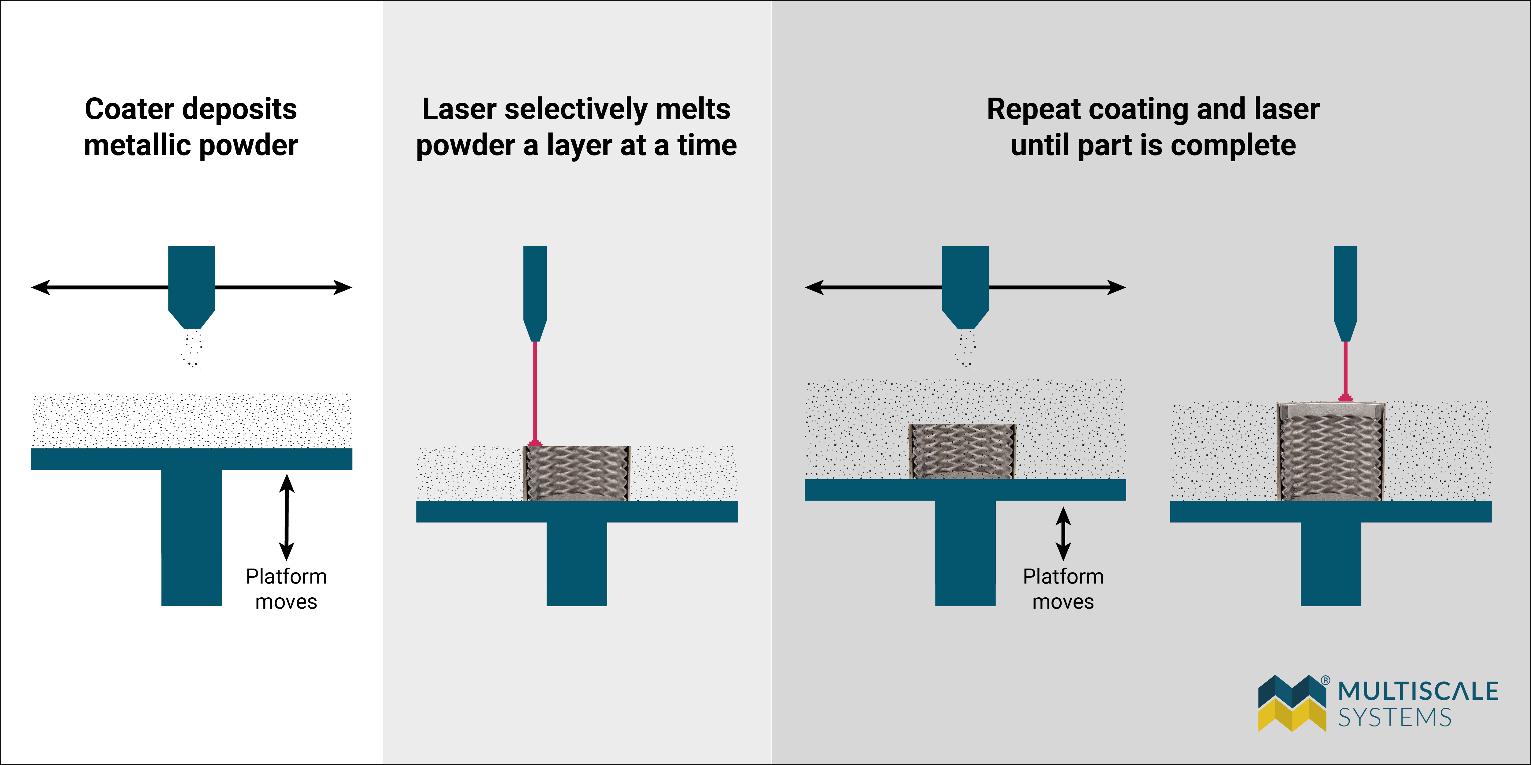
Figure 4: Powder bed fusion starts with a sandbox of metallic powder adjacent to a moveable platform. A coating device (much like a windshield wiper) coats the moveable platform with a layer of metallic powder that is then selectively melted using a laser. The coater then deposits another layer of powder and the process repeats until an entire part is created.
Laser powder bed fusion: Pros and cons
Pros:
- Can be used to make complex structures, including lattices
- Reduced manufacturing time compared to conventional subtractive methods
- No sintering required
Cons:
- Atomized powder can be expensive to source
- Stringent safety precautions must be followed
- Machinery is expensive
- Parts are still porous and may suffer failure due to creep and fatigue
Method 3: Hybrid additive CNC with laser wire direct energy deposition
Laser wire direct energy deposition
Laser wire direct energy deposition (DED) is an attractive alternative to metal AM powder methods. Instead of relying on powder – which requires processing and presents considerable safety issues – laser wire DED uses standard welding wire spools. The spools of wire are fed into the printer similarly to an FFF machine, but instead of simply being extruded from a nozzle at the point of assembly, the wire is laser welded to the previously deposited layer.
There are multiple benefits to a wire fed DED process. Because the wire is being laser welded layer by layer, the final part has a much higher density than either FFF or LPBF and, in most cases, the part has strength and porosity indistinguishable from a forged or cast part.
The wire feedstock is the same as conventional welding wire and can be sourced quickly and easily from traditional vendors without the cost and wait associated with powder materials. The storage of welding wire is straightforward, and there are no specialized requirements for handling the materials above standard protective and safety precautions.
A disadvantage of this process is that the resolution is relatively coarse – as it is set by the size of the weld bead – which is generally on the order of the wire radius. As a result, the final part may need to be turned or milled to achieve the appropriate shape and surface finish.
Hybrid additive CNC
To solve this issue of course parts, at Multiscale Systems we incorporate our laser wire DED method directly into a 5-axis vertical CNC mill. With a hybrid additive CNC we build the part from the ground up, with machining steps occurring as needed during the additive process. This technique allows for large travel distances on the print head so that we can build larger parts.
Turning, drilling, and finishing can all be done with the same machine and complex geometric features can be created that would not be possible using additive or subtractive manufacturing methods on their own. The best part of hybrid additive CNC is the ability to use more than one material. Our dual-wire machine allows for a quick swap between wires so that we can create metamaterial composites from a variety of alloys.
Hybrid additive CNC: Pros and cons
Pros:
- Ability to create larger parts
- Higher density parts compared to FFF or LPBF, with strength and porosity similar to forged or cast parts
- Materials cost less than powder, have no special storage requirements, and can be sourced quickly and easily from traditional vendors
- No special safety or material handling requirements
- Turning, drilling, and finishing can be accomplished with the same machine
- Complex geometric features and mixed alloys within the same part are possible
Cons:
- Expensive machinery
Conclusion
Not all additive manufacturing processes are the same, and it makes all the difference when designing a part or system that has particular engineering requirements. If you need a high-strength, low-cost part to replace plastic components then FFF metal might be exactly what you’re looking for. But if you need a high-temperature, fatigue-critical part with a mirror finish then hybrid additive CNC is the way to go.
| Bound metal 3D printing | Laser powder bed fusion | Hybrid additive CNC | |
|---|---|---|---|
| Pros |
|
|
|
| Cons |
|
|
|
We’ve made metamaterial composite parts in stainless steel 17-4 PH fabricated with FFF bound metal, all metal expansion joints in SS316L using LPBF, and Nickel 718 roller bearings using hybrid additive CNC; each of these components serve different purposes, and use different methods to make them.
If you’re interested in seeing which metal additive process is right for your project, contact us to get started.
 Art Evans, Ph.D. is the CTO and Research Director at Multiscale Systems. With a background in physics research, numerical analysis, and computational continuum mechanics, Art leads technology development and research projects.
Latest Lab Notes

News /
July 18, 2025—Multiscale will engineer functionally-graded alloys tailored for molten salt and liquid metal environments, leveraging its hybrid manufacturing systems to produce nuclear-grade material performance.
News /
March 11, 2025 – Multiscale Systems to showcase cutting-edge industrial innovation during StartUp Week Worcester 2025.

News /
Multiscale Systems receives Massachusetts manufacturing award in recognition of outstanding leadership skills in the manufacturing industry.

